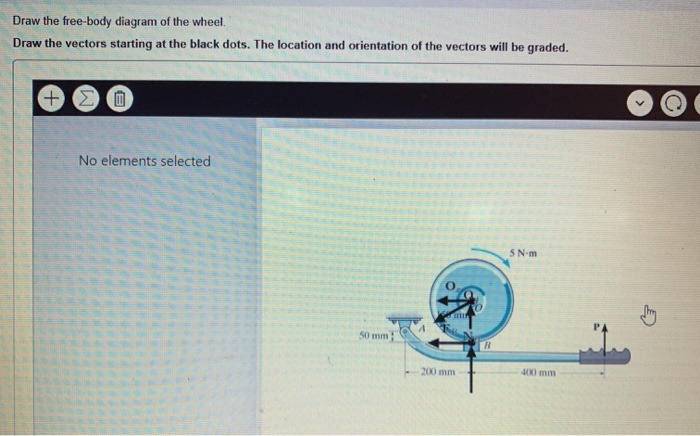
View Available Hints No elements selected 06 m 60 mm lecture9_an lecture7 animal1pdf 9. Draw the vectors starting at the black dots.

Free Body Diagram Of The Wheel Download Scientific Diagram
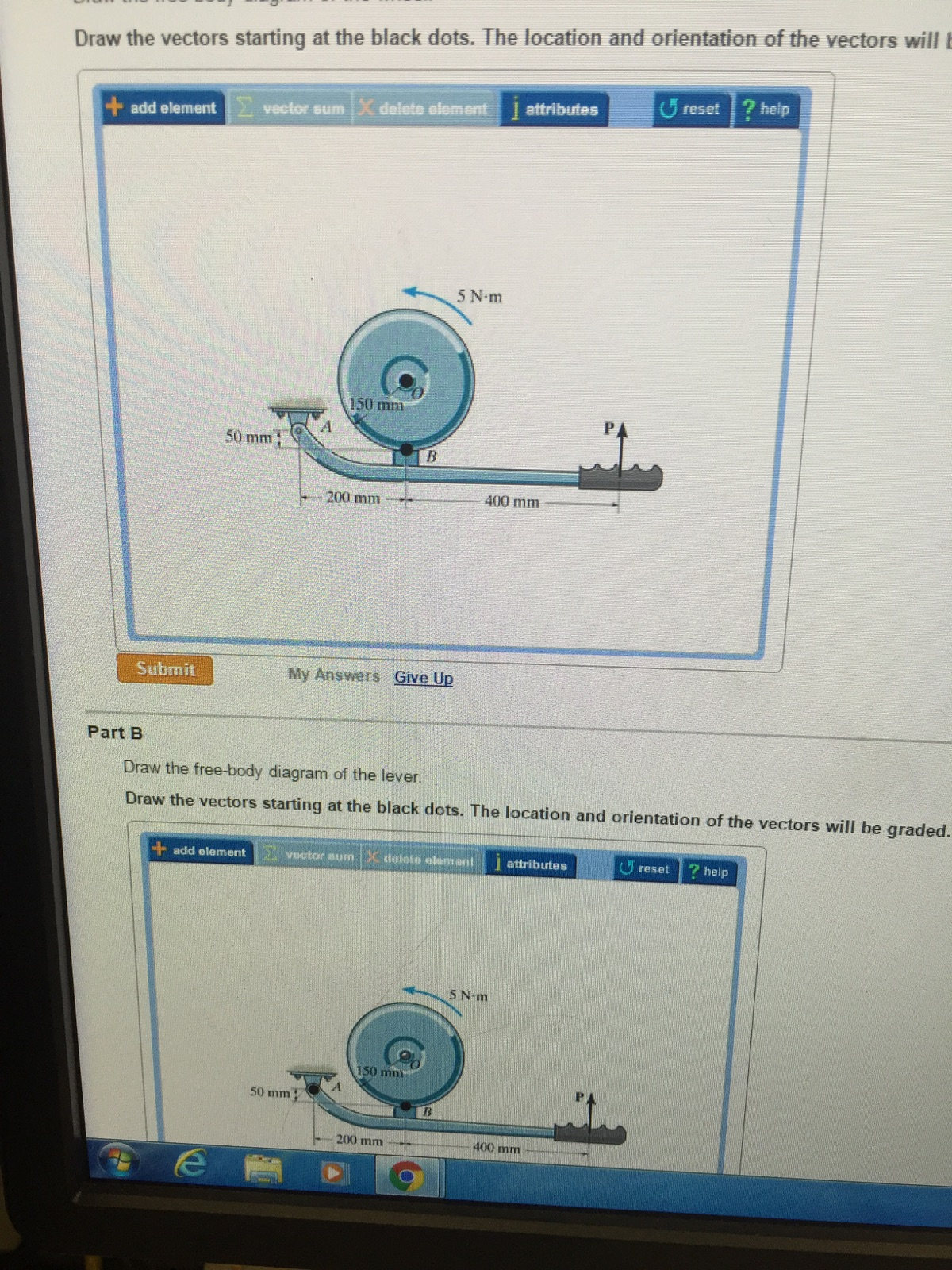
The location and orientation of the vectors will be graded.
. A short video to show how to form an imaginary cut and draw a free body diagram of a simply supported beam with a point loadRelated videosReactions of a Si. Thats it for the free body diagram of this block. The location and orientation of the vectors will be graded.
Imagine the body to be isolated or cut free from its constraints and draw its outlined shape. Also the hold a blue guide as well the two guides are contacting with this red block. The hydraulic cylinder AD acts as a two-force member and there is a pin connection at B.
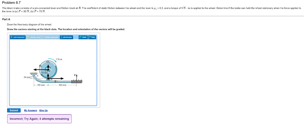
Add elementvector sum X delete element I attributes U reset. Draw the vectors starting at the black dots. ItItisispin-connected pin-connectedatat its center C and at its outer rim is a ratchet gear having a mean A 502mm in.
The only rule for drawing free-body diagrams is to depict all the forces that exist for that object in the given situation. The sum of the forces acting on the 5 holes should equal 650 kgf. A horizontal force F is applied to the axle of the wheel.
1D A baseball just before it leaves the bat. Free Body Diagrams on a LooptheLoop Roller Coaster Draw the free body diagrams for a coaster at the boom and top of a loop and write the equaons for the net force. Note that the moment arms for the two spring forces are computed assuming a small angle θ.
12pts 1A A coaster sitting under a cup of coffee. Mg F net F N F net ma ma c The net force in the loop must be centripetal force F net F N. Mar 10 2022 1034 AM.
You can draw a free-body diagram of an object following these 3 steps. There is no hard and fast rule about the number of forces that must be drawn in a free-body diagram. Sketch what is happening.
Problem 88 Thanks Question. Draw the free-body diagram of the wheel Draw the vectors starting at the black dots. The springs are identical and an extra mass of 50 grams stretches The mass-spring equation as a rst order linear di erential system Team Member.
Draw a free-body diagram for the car. Free-body diagrams are important because they allow us to analyze an object in isolation without distractions. The hydraulic cylinder AD acts as a two-force member and there is a pin connection at B.
1B A car slowing down as it approaches a stop sign. The open loop transfer function is given by. The car shown below is moving and then slams on the brakes locking up all four wheels.
It is pinned at A and rests against the smooth horizontal member at B. We must draw a separate free-body diagram for each object in the problem. Determine the moment required to initiate the rotation of the wheel and whether or not it is possible for the wheel to roll up the wall.
Draw a free body diagram of the car as it comes to a stop. Draw an outlined shape. Draw the free-body diagram of the wheel and member ABC used as part of the landing gear on a jet plane.
Draw The Free Body Diagram Of The Wheel. 1C Your test stuck to your fridge by a magnet. Wheel is supported by a freely-rotating roller and the wall.
The weight and radius of the wheel are W 250 N and r 0340 m respectively. C M K Time sec. Show your result in side view.
You should think this Web-site has an affiliate partnership andor A different material relationship into the people or corporations outlined in or connected to from this page and should receive commissions from buys you make on subsequent Websites. Introductory Control Systems PID Control of a Spring-Mass-Damper SMD Position Fig. Draw the free-body diagram of the wheel and member ABC used as part of the landing gear on a jet plane.
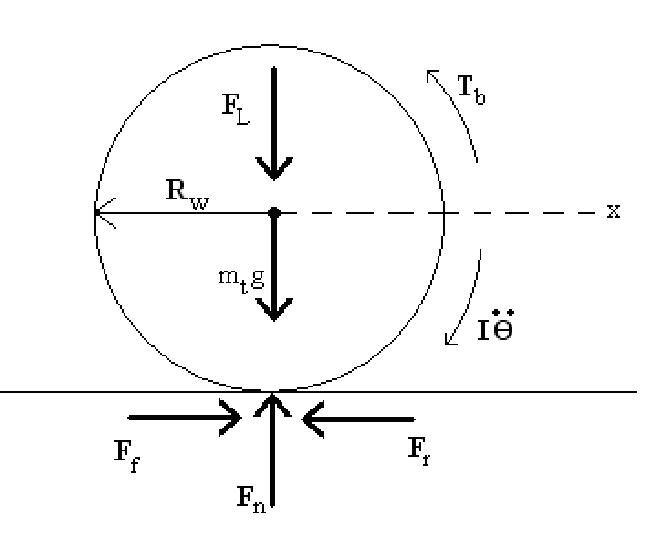
Draw the free-body diagram of the wheel. Eulers equation can then be applied about point O to minimize the number of equations needed. Idealized model Free-body diagram FBD 1.
I figured it is first necessary to draw a free body diagram of the entire wheel and then apply the method of sections in which I would make cuts along specific regions of the wheel and determine the forces acting on them. Write all the modeling. Draw the free-body diagram of the winch which B 3 in.
To draw a free-body diagram we draw the object of interest draw all forces acting on that object and resolve all force vectors into x and y-components. Draw the vectors starting at the black dots. Label any necessary dimensions.
So you have x and y components in the the string components and the mg. Draw the free body diagram of the wheel. Determine the forces that act on the object.
Help 5 N m 150 mm 50 mm 200 mm Submit My Answers Give Up Incorrect. 7 hours agoSingle spring From the free-body diagram in Fig. Consists of of aadrum drumofofradius radius 4 mm.
Two one with the string one with the surface. Draw the vectors starting at the black dots. Show all the external forces and couple moments.
Draw the object in isolation with the forces that act on it. Draw the free body diagram of the wheel. Draw free body diagrams for the following objects.
Draw the free body diagram of the wheel Materials Link DISCLOSURE. Free-Body Diagram Example 4. FREE-BODY DIAGRAMS Section 52 2.
Radius ofof 6150 in. How to draw a free-body diagram. Draw the free-body diagram of the wheel and member ABC used as part of the landing gear on a jet plane.
Draw the free-body diagram of the uniform trash bucket which has a significant weight. The next step is to draw the free body diagram of the wheel as shown below. If given a description of a physical situation begin by using.
Draw a free body diagram showing all forces and their directions Write equation of motion and derive transfer function of response x to input u chp3 15. The drawing shows a bicycle wheel resting against a small step whose height is h 0120 m. Draw the vectors starting at the black dots.
Thus to construct free-body diagrams it is extremely important to know the various types of forces. Connected to wheel using a flexible cable without skip on wheel. The distance between the two wheels is 8 feet and the center of mass is 3 feet behind and 25 feet above the point of contact between the front wheel and the ground.
A Draw the free-body diagram showing the forces that act on the wheel. Ad Over 27000 video lessons and other resources youre guaranteed to find what you need. A applied loads b support reactions and c the weight of the body.
Below Ive drawn a free body diagram of the wheel. So first to draw the free body diagram free the body. Part B Draw the free body diagram of the lever.
Public Domain image no author listed.

Free Body Diagram Of A Wheel Download Scientific Diagram
Solved Part A Draw The Free Body Diagram Of The Wheel Draw Chegg Com
1 Free Body Diagram Of A Wheel Download Scientific Diagram

Free Body Diagram Of A Rolling Wheel Download Scientific Diagram
Solved Part A Draw The Free Body Diagram Of The Wheel Draw Chegg Com
Solved Draw The Free Body Diagram Of The Wheel Draw The Chegg Com
Free Body Diagram Of A Wheel Download Scientific Diagram

Solved Draw The Free Body Diagram Of The Wheel Draw The Chegg Com
0 comments
Post a Comment